How to Determine the Correct Wire Size for Feeder Supplying Multiple Motors?
In previous sections on motor circuit calculations, we determined conductor sizing, overcurrent protection, and overload protection with solved examples for a single-motor circuit. In this section, we will determine the sizing of a feeder circuit supplying multiple motors on the same phase.
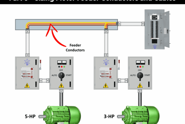
Sizing Feeder Conductor Supplying Multiple Motors
NEC 430.53 permits two or more motors on the same branch circuit in accordance with 430.53(A) through (D). According to 430.25, the ampacity of conductors supplying multi-motor and other load circuits must not be less than the marked ampacity on the equipment nameplate, as specified in 430.7(D). If the nameplate rating is unavailable, the conductor ampacity must be determined based on 430.24.
According to the 430.24, the ampacity of conductors supplying multiple motors must not be less than:
- 125% of the full-load current (FLC) of the highest-rated motor (430.6(A), 430.17 & 430.24).
- The sum of the FLCs of all other motors on the same phase (430.6(A)).
- 100% of non-continuous loads and 125% of continuous non-motor loads on the feeder.
According to 430.26, If all motors do not operate simultaneously (all motor running at a time), feeder demand factors may be applied to reduce the calculated ampacity per NEC 430.24. However, the conductors must have sufficient ampacity to handle the maximum load based on the size and number of motors.

Example 1 – Sizing Feeder Conductors for Single Phase Motors
Determine the required feeder conductor size (THHN) with a 75°C terminal rating for a system supplying two 230V single-phase motors: one rated at 2 HP and the other at 10 HP.
Solution:
1: Determine FLC of Each Motor
Based on Table 430.248, the full-load current in amperes for single-phase AC motors at 230V are as follow:
- FLC of 2 HP Motor = 12A
- FLC of 10 HP Motor = 50A
2: Determine the Total Ampacity
The ampacity of feeder circuit supplying multiple motors can be calculated in accordance with 430.24(A). Since the largest motor is 50A based on FLC;
50A × 1.25 = 62.5A.
Now, sum app with the FLC of other motor(s).
62.5A + 12A = 74.5A.
2: Determine the Size of Feeder Conductors
The suitable wire size can be selected from the Table 310.16. For a feeder supplying 74.5A of current with a 75°C terminal rating, the right size of feeder conductor is #4AWG cupper or #6AWG aluminum (THHN).
Example 2 – Sizing Feeder Conductors for Multi-phase Motors
What is the required size of feeder conductor (THHN) at 75°C terminal rating supplying the following multiphase motors?
- Three 1.5 HP, 115V, 1-Phase motors
- Three 7.5 HP, 208V, 1-Phase motors
- One 40 HP, 460V, 3-Phase squirrel cage or wound rotor motor
Solution:
1 – Find the Full Load Current of Each Motor
The full load current (FLC) can be determined using Table 430.248 and 430.150 for single-phase and three-phase AC motors respectively.
- FLC of 1.5 HP, 115V, 1-Φ motor = 20A
- FLC of 7.5 HP, 208V, 1-Φ motor = 44A
- FLC of 40 HP, 460V, 3-Φ squirrel cage or wound rotor motor = 52A
2 – Calculate the Total Ampacity
As previously stated, the ampacity of conductors supplying multiple motors must not be less than 125% of the full-load current (FLC) of the highest-rated motor (per NEC 430.6(A) and 430.24). Additionally, the FLC values of all other motors connected to the same phase must be added to the FLC of highest-rated motor multiplied by 1.25 (per NEC 430.6(A)).
Thus, the total ampacity is calculated as follows:
(52A×1.25) + 44A + 44A + 20A = 173A.
3: Size The Feeder Conductors
The size of feeder conductor supplying 173A of multiple motors circuits with a 75°C terminal rating, Table 310.16 suggests (THHN) conductors for the feeder:
- #2/0AWG cupper
- #4/0 AWG aluminum
When sizing a feeder conductor supplying multiple motors, only the motors on the same phase should be considered for additions of FLCs. This is why our calculations include four motors instead of all seven.
The same rule applies when sizing protection for feeder conductors, as they must be protected against motor overload and overcurrent caused by short circuits, and ground faults (Discussed in the next part).
Series Overview: Motor Circuit Calculations
Resources & Tutorials:
Wire Sizing Guides


Leave a comment