Why is a Capacitor Bank Connected in Parallel and Not in Series for Power Factor Correction?
Capacitor banks are used to improve power factor and voltage regulation in electrical systems. These banks consist of multiple capacitors grouped together and are primarily connected in parallel to the electrical system. In the following articles, we will explain the rationale behind connecting capacitor bank in parallel for power factor correction, discuss the consequences of series connections with inductive loads, and provide solved examples and calculations to illustrate the principles involved.

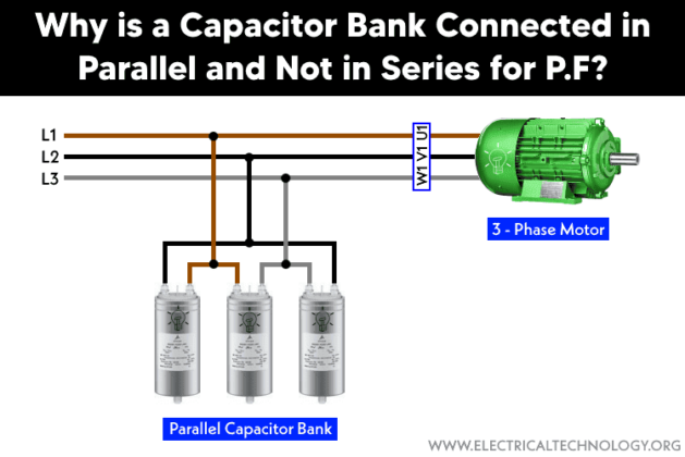
Why is Capacitor Bank Connected in Parallel?
Capacitor banks are connected in parallel with the low voltage load to directly provide reactive power (VARs) to the system, improving the power factor and voltage stability.
These power factor improvement capacitors are connected in parallel rather than in series due to the following reasons:
Increase in Capacitance
When capacitors are connected in parallel, their total capacitance is the sum of the individual capacitances:
CTotal = C1 + C2 + C3 + … Cn
This makes it easier to achieve the desired capacitance for the system.
On the other hand, In series, the total capacitance is reduced in series:
1/CTotal = 1/C1 + 1/C2 +1/C3 + … 1/Cn
Hence, a series connection would decrease the overall capacitance, which is usually not desired.
Voltage Distribution
In a parallel configuration, each capacitor is subjected to the same voltage as the supply, which ensures consistent performance.
In a series configuration, the voltage divides across the capacitors, potentially leading to uneven voltage stress. If the capacitors are not identical, this uneven distribution can damage the capacitors.
Energy Storage
Capacitor banks are used for purposes such as power factor correction, voltage regulation, and energy storage. In parallel, they can store more energy, as energy stored is proportional to capacitance:
E = (1/2)CV2
As a result, Increasing the total capacitance increases the energy storage capability.
Fault Tolerance
In parallel connected capacitors, if one capacitor fails, the others can continue to function, maintaining the system’s operation with reduced capacity.
In contrast for series connected capacitors, the failure of one capacitor disrupts the entire series string, leading to system failure.
Ease of Maintenance
Parallel configurations allow individual capacitors to be added, removed, or replaced without significantly affecting the entire system.
On the other hand, a series configuration complicates maintenance, as all capacitors are interdependent.
Due to the above reasons, a parallel arrangement of capacitors to the load ensures:
- Reactive Power Support: By being parallel to the load, the capacitor bank supplies reactive power locally, reducing the reactive power demand on the source or transformer.
- Voltage Regulation: A parallel capacitor bank helps maintain stable voltage levels by compensating for the voltage drop caused by inductive loads.
- Independent Operation: The voltage across each parallel capacitor remains the same as the system voltage, making it straightforward to size and manage the bank for the desired compensation.
Applications of Parallel Capacitor Banks
Parallel capacitor banks are commonly used in:
- Power factor correction in electrical grids.
- Voltage stabilization in distribution systems.
- Harmonic filtering to improve power quality.
Related Post: Capacitor Bank in kVAR & µF Calculator for Power Factor Correction
Example:
An industrial facility operates a 400 V, 50 Hz, 3-phase system with an inductive load drawing 100 kVAR. To improve the power factor from 0.8 to 0.95, a capacitor bank is designed to provide 47.39 kVAR of reactive power. The required capacitance is calculated as follows:
Where:
- is the reactive power supplied by the capacitor bank (in kVAR).
- ω = 2πf is the angular frequency of the system.
- f = is the supply frequency in Hz
- V is the phase-to-phase voltage of the system (400 V in this case).
- is the capacitive reactance (1 ÷ XC = ωC).
Capacitive Reactance (XC):
XC = V2 ÷ QC
Substitute V = 400 V and QC = 47.39 kVAR
= (400)2 ÷ 47.39 kVAR
≈ 3.377Ω
The capacitive reactance is related to capacitance by the formula:
= 1 ÷ ωC
Rearranging for C:
C = 1 ÷ ω
Substitute ω = 314.16 rad/s and :
C = 1314.16 × 3.377
C = 1 ÷ 1,061.42
C ≈ 0.000942 F
The required capacitance for the capacitor bank is:
C = 942 μF.
Thus, the required capacitor bank should have a total capacitance of approximately 942 μF in parallel.
Hence, the proper value of capacitor bank connected in parallel cancels out the reactive power drawn by the inductive load. The power factor improves from 0.8 to 0.95 as needed according to the system requirement. That is why a capacitor bank is always connected in parallel with the inductive load for power factor improvement.
What Happens if a Capacitor Bank is Connected in Series with an Inductive Load?
1. Impedance Interaction: In a series connection, the total impedance becomes a combination of the capacitive reactance (XC) and inductive reactance (XL). The resultant impedance is given by:
This interaction may lead to undesirable resonance if , causing an extremely high current to flow through the circuit.
2. Voltage Imbalance: When connected in series, the voltage across the capacitor bank can become excessively high due to the series reactance. This overvoltage may exceed the capacitor’s voltage rating, leading to potential damage or failure.
To prevent overvoltage, we need the following parameters:
VL = VS ⟹ |ZC + ZL| = |ZL|
But the series connected capacitor will deliver across the load:
VL = VS = |ZL ÷ (ZC + ZL)|
Since the total impedance (ZTotal) remains the same, the series-connected capacitor bank will draw the same amount of apparent power (in kVAR) as before. Consequently, the desired improvement in the overall scenario is not achieved, defeating the purpose of power factor correction.
3. Reduced Reactive Power Compensation: Unlike a parallel connection, where the capacitor supplies reactive power, a series connection can hinder compensation as it interacts directly with the load’s reactance rather than supplying VARs to the system.
Example:
Consider the same 400 V, 50 Hz, 3-phase system with an inductive load of and a capacitor bank with connected in series.
Inductive Reactance (XL):
XL = V2 ÷ QL
Substitute V = 400 V and QL = 100 kVAR
= (400)2 ÷ 100 kVAR = 1.6 Ω
Total Reactance (X):
Since the inductor and capacitor are in series, their reactances subtract:
XTotal = −
Substitute = 1.6 Ω and XC = 3.377 Ω
XTotal = 1.6 − 3.377 = −1.777 Ω
A negative XTotal indicates that the circuit is capacitive overall.
In a series circuit, the total impedance ZTotal is the sum of the inductive reactance and capacitive reactance. Since the two reactances oppose each other, the total reactance is:
ZTotal = √(R2 + ( − )2)
This ≈ zero-impedance condition creates a resonant circuit, causing current to surge to infinity in an ideal system. In practical systems,
As a result, the parallel configuration ensures higher capacitance, consistent voltage, better energy storage, and system reliability, making it the preferred choice for capacitor banks in electrical systems. That is why capacitor banks are connected in parallel rather than series for P.F correction in low voltage systems.
Other applications of series capacitors banks are for compensation of long transmission lines, voltage control in substations and series resonance applications.
Resources:


Leave a comment